In the early days of oil discovery in Lambton County, oil flowed at such a velocity that drillers had only to be on-hand to capture the continuous flow. If there was not enough pressure at the bottom of the well to force the oil out then the oil had to be pumped out. Initially this was a task done by hand as one man stood at the well, lifting and pushing on a pump handle much as he would on a water pump, to fill tanks and barrels with the resulting flow of oil.
By the 1860s, it became the standard to use steam engines to power the oil well pumps. With this system, each individual well required its own steam engine which would be housed a short distance away in a protective wooden structure, along with a boiler to supply power to the steam engine. Once the steam engine was engaged, it would drive a pulley which was connected to a vertical bullwheel by a leather belt. The bullwheel then would turn a shaft which had a crank in the centre, converting the rotary motion of the bullwheel into an up-and-down movement. A walking beam was supported at its centre point by a wooden post in such a way as to allow it to rock up and down as it was pulled by the crank shaft. Finally, as the walking beam moved it would pull on the top of a sucker rod which worked the pump inside the well shaft.
The pump itself moved oil to the surface by creating a vacuum inside a tube which ran the length of the well. At the very bottom of the well was a length of perforated pipe which kept the pump anchored to the bottom of the well. The perforations allowed the oil to enter the pump. Next, two valves regulated the movement of the oil. A standing, or lower, valve remained in place and a working, or upper, valve moved up and down as the walking beam pulled on the sucker rods. Each of these valves was topped with a cage containing a ball. As the working valve was raised, the ball on the standing valve rose while the ball on the working valve dropped which sucked oil into the pipe, similar to placing a finger over a straw to hold liquid. When the working valve was lowered, the positions of the balls would reverse, forcing the oil up the pipe where it could travel to a collection tank.
Oil Drilling Techniques: Single-Well Systems
Video clip. Shows how a single-well system works.
Duration: 00:23 - Transcription
This one-well-one-engine system was expensive and time consuming to maintain and repair. Steam engines were quite large and in some fields where wells were placed close together, this posed a problem. In 1863, John H. Fairbank joined two well-pumps to one steam engine and the jerker line system for pumping oil was born.
Today, the active wells in Lambton County are powered by a combination of multiple- and single-well systems. Small diesel-powered, or even solar-powered, motors provide an efficient means of pumping wells that otherwise would be far from a central power source.


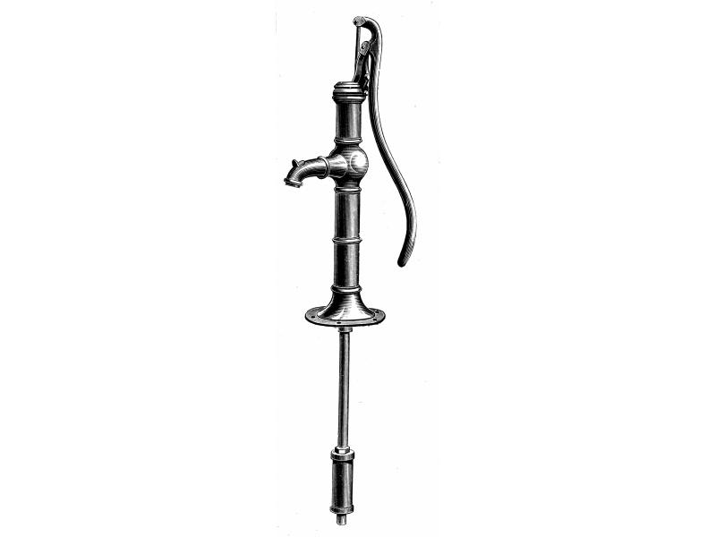 Hand-pumps were used for the earliest oil wells.
Source: Oil Well Supply Company Ltd., Petrolia Catalogue, 1917.
 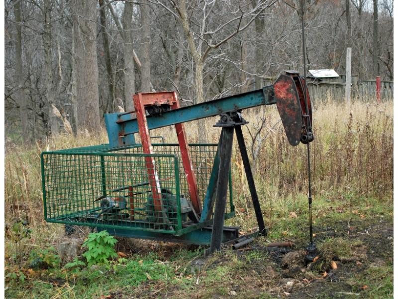 Modern single-well pumping rig powered by a diesel engine.
 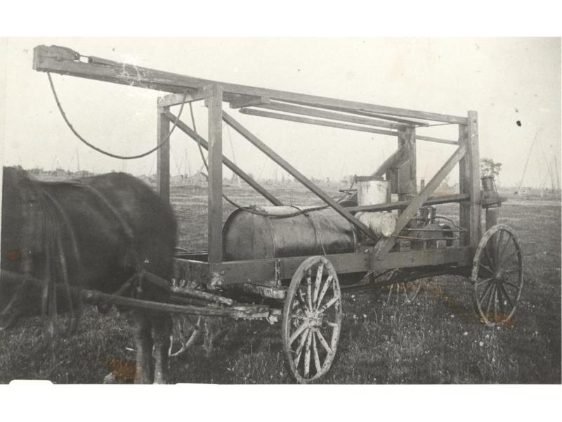 The crude oil dipping machine, invented by Henry Gregory, was used at wells which did not produce enough oil to put up equipment for pumping the oil to the surface. The machine ran a bailer down to the crude oil and was pulled back up to the surface to be dumped.
 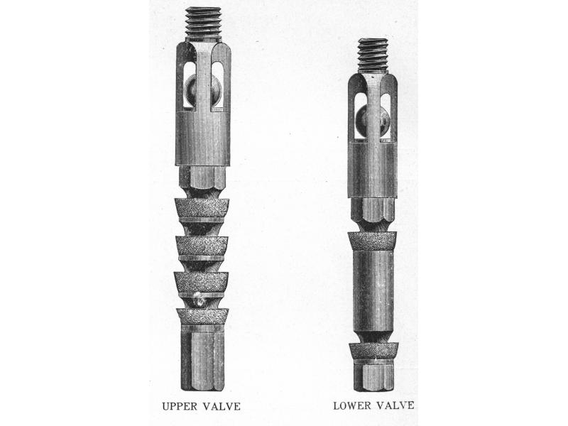 Upper and lower valves showing leather cups which form a seal, creating a vacuum within the pump, and the ball bearings which suck the oil into the pump.
Source: Oil Well Supply Company Ltd., Petrolia Catalogue, 1917.
 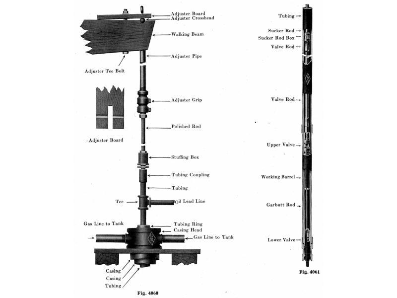 The fittings of an oil well pump, from the walking beam down to the lower valve.
Source: Lucy Manufacturing Corporation Catalog No. 9, 1921.
 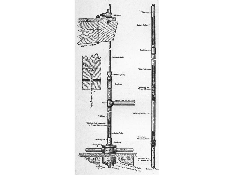 The fittings of an oil well pump, showing the perforated pipe which anchors the pump to the bottom of the well, and the pipe near the top which sends the oil into a separating tank.
Source: Oil Well Supply Company General Catalogue No. 29, 1911.
Add new comment